Do’s and Don’ts
Designing with Cast Stone
Cast Stone Institute recommendations.
“L” Shapes and “U” Shapes
The coping section shown in Fig. 1 creates crack initiation points and will cost more than either of the alternative sections shown due to more labor intense molding, manufacturing, shipping and setting operations.
“L” Shapes and “U” Shapes
Fig. 2 shows a header with a long horizontal soffit. This is not recommended as any movement will cause stress resulting in a fracture at this location.
“L” Shapes and Feather Edges
Fig. 3 illustrates the two recommended corner conditions – the butt joint and the quirk meter. The feather edge illustrated on the left is very weak and prone to chipping.
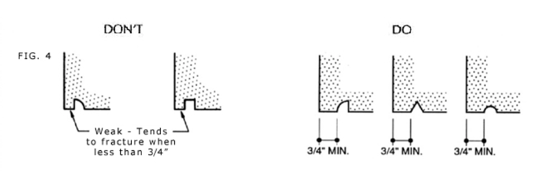
Drips and Reglets
Deep drips or drips with no draft serve no better purpose than the three drips shown on the right. The “V” and half round types are simple to manufacture, work just as well and can endure more abuse.
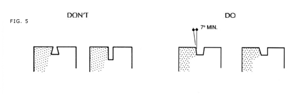
Anchor Slots
A minimum of Seven (7) degrees of draft formed flashing and anchor slots to ensure crisp, straight edges during the demolding process.
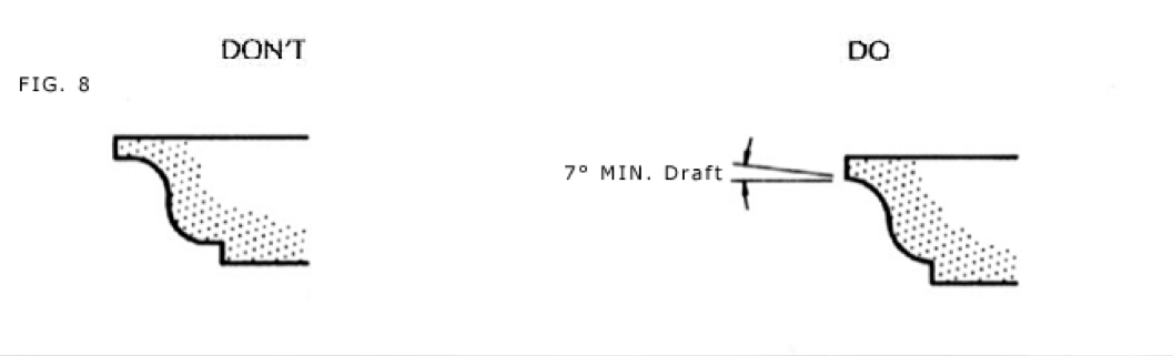
Draft
Projecting portions of sections, in general, should not exceed their thickness. A minimum of 7 degrees of draft is needed to separate the production pieces from the mold and may be provided by the manufacturer even where 90 degrees is shown on the drawings.
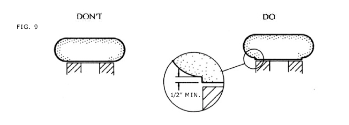
The intersection of the unexposed of back side with the formed sides should not come to a feather edge in the mold. This can be avoided by using a shoulder.
Radius Pieces
When setting space allows, make curved veneer pieces straight on the back, this allows the stone to be efficiently demolded during the production process.